9.5 ACCOMMODATION OF ANGULAR MOVEMENTS
9.5 Installation plan
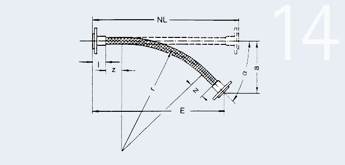
Elbow
Dimensions in mm
| Nominal width range DN | Up to 12 | 16-25 | 32-40 | 50-100 | 125-150 | 200-300 |
|---|---|---|---|---|---|---|
| Length details | 25 | 50 | 75 | 100 | 150 | 200 |
| E | mm | installation length |
| NL | mm | total length of the metal hose |
| r | mm | smallest bending radius |
| l | mm | length of a connection part |
| a | mm | angling distance |
| z | mm | length details for neutral hose ends (see table) |
| bending angle |
Example 14
Example
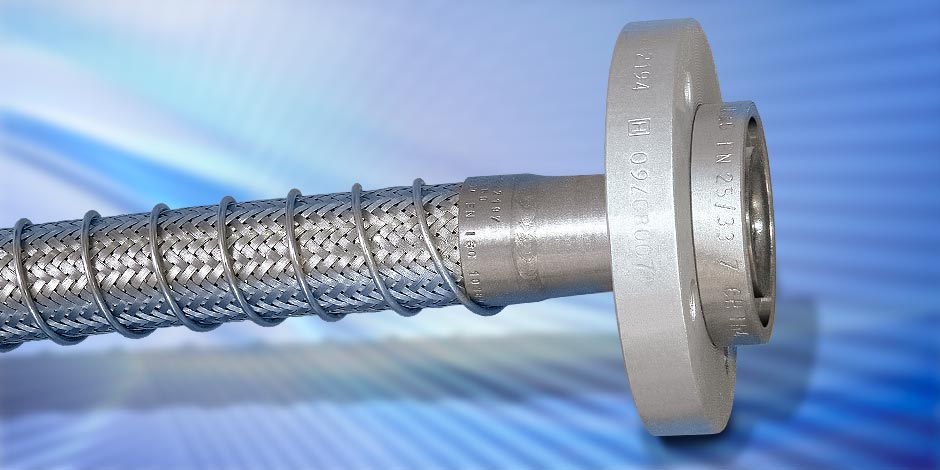
Rattay stainless steel corrugated hose DN 50 Type HR I/S, on both sides screw connections made of stainless steel, Fig. 114.
Operating data
 = 48°
= 48°
Calculation:
l = 111 mm
r = 310 mm see hose table
z = 100 mm see table
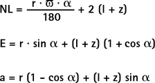
a = 360 (1 - cos 48°) + (111 + 100) sin 48° = 276 mm
NL = ![]() + 2 (111 + 100) = 723 mm (Order length NL = 730 mm)
+ 2 (111 + 100) = 723 mm (Order length NL = 730 mm)
E = 310 · sin 48° + (111 + 100) · (1 + cos 48°) = 620 mm